Sma SB 6000TL‑US Installation User Manual
Browse online or download User Manual for Equipment Sma SB 6000TL‑US Installation. SMA SB 6000TL‑US Installation User Manual
- Page / 92
- Table of contents
- BOOKMARKS
Rated. / 5. Based on customer reviews
SB6-11TL-US-IA-en-13 | IMUS-SB8-10TLUS | Version 1.3
CA
US
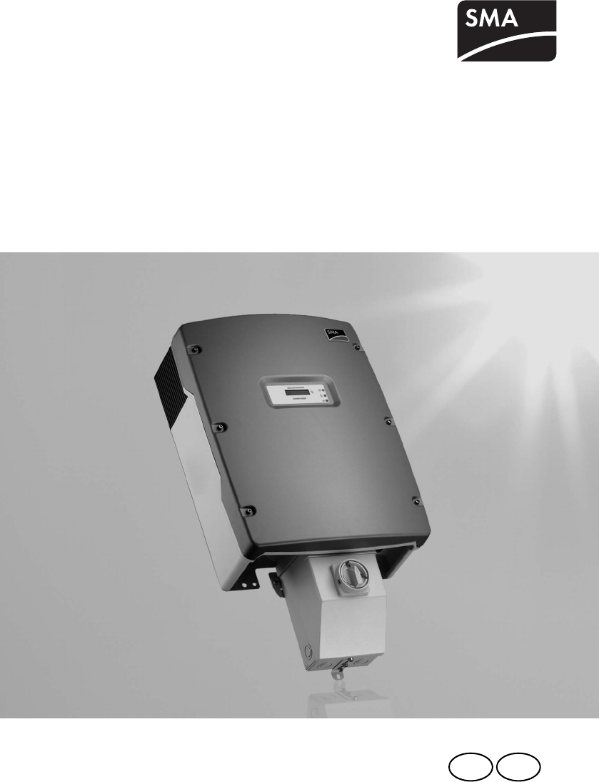
PV Inverter
Sunny Boy 6000TL‑US/7000TL‑US/8000TL‑US/
9000TL‑US/10000TL‑US/11000TL‑US
Installation Manual
- PV Inverter 1
- IMPORTANT SAFETY INSTRUCTIONS 4
- Warnings on this product 5
- General Warnings 6
- Table of Contents 7
- SMA America, LLC 10
- 1 Information on this Manual 11
- 2.1 Intended Use 12
- PV plant design 13
- Grounding the PV modules 14
- 2.2 Safety Precautions 15
- 3 Unpacking and Inspection 16
- 3.3 Position of the Stickers 17
- 3.4 Identifying the Sunny Boy 18
- 4Mounting 19
- Requirements 20
- Recommended clearances 21
- 4 Mounting SMA America, LLC 22
- Mounting on a Stone Wall 23
- Supporting Posts 23
- Inserting the DC varistors 25
- SMA America, LLC 4 Mounting 27
- 5 Electrical Connection 28
- AC Grounding 29
- PV Grounding 29
- DC Grounding Conductor 29
- 5.4 AC Connection 33
- System configuration 34
- AC cable requirements 34
- Load Disconnection Unit 35
- 2357 AB+ 37
- 5.5 DC Connection 39
- 5.5.1 DC Cable Requirements 40
- 5.6 Communication 42
- 6Commissioning 43
- 7 Displays and Messages 47
- 7.2 Display Messages 48
- Feed-in operation 49
- Disturbance 49
- PV overvoltage 50
- 7.3 LED Display 51
- Feed-in Operation 52
- Disturbance or Fault 52
- PV Overvoltage 53
- Ground Fault 53
- 8 Opening and Closing 55
- 8.2 Closing the Sunny Boy 56
- 8.3 Opening the DC Disconnect 58
- 8.4 Closing the DC Disconnect 59
- 9Maintenance 60
- Cleaning the Fans 61
- 9.4 Checking the Fans 63
- Fitting the Jumpers 64
- 9.5.1 DC Varistors 65
- 9.5.2 AC Varistors 67
- 10 Decommissioning 68
- 10.2 Packaging the Sunny Boy 69
- 10.3 Storage 69
- 10.4 Disposal 69
- 11 Technical Data 70
- Protection Devices 71
- General Data 71
- Efficiency 71
- 11.2 Sunny Boy 7000TL-US 72
- Grid Connection 73
- Ambient Conditions 74
- Mechanical Data 74
- 11.3 Sunny Boy 8000TL-US 75
- 11.4 Sunny Boy 9000TL-US 77
- 11.5 Sunny Boy 10000TL-US 80
- 11.6 Sunny Boy 11000TL-US 82
- 11.7 DC Disconnect 85
- Measurement accuracy 86
- *see National Electrical Code 87
- , 310.16 87
- Spare parts 88
- Accessories 88
- 13 Compliance Information 89
- 14 Contact 90
- XXX4."4PMBSDPN 92
Summary of Contents
Page 1 - PV Inverter
SB6-11TL-US-IA-en-13 | IMUS-SB8-10TLUS | Version 1.3CAUSPV InverterSunny Boy 6000TL‑US/7000TL‑US/8000TL‑US/9000TL‑US/10000TL‑US/11000TL‑USIns
Page 2
SMA America, LLC10 SB6-11TL-US-IA-en-13 Installation Manual
Page 3
SMA America, LLC 1 Information on this ManualInstallation Manual SB6-11TL-US-IA-en-13 111 Information on this Manual1.1 ValidityThis manual describes
Page 4 - IMPORTANT SAFETY INSTRUCTIONS
2 Safety SMA America, LLC12 SB6-11TL-US-IA-en-13 Installation Manual2Safety2.1 Intended UseThe Sunny Boy is a PV inverter which converts the DC curre
Page 5 - Warnings on this product
SMA America, LLC 2 SafetyInstallation Manual SB6-11TL-US-IA-en-13 13Principle of a PV Plant with a Sunny BoyThe Sunny Boy may only be operated with P
Page 6 - General Warnings
2 Safety SMA America, LLC14 SB6-11TL-US-IA-en-13 Installation ManualGrounding the PV modulesThis Sunny Boy is a transformerless inverter. That is why
Page 7 - Table of Contents
SMA America, LLC 2 SafetyInstallation Manual SB6-11TL-US-IA-en-13 152.2 Safety PrecautionsHigh voltages in the inverterElectric shock when touching l
Page 8
3 Unpacking and Inspection SMA America, LLC16 SB6-11TL-US-IA-en-13 Installation Manual3 Unpacking and InspectionCheck the delivery for completeness a
Page 9
SMA America, LLC 3 Unpacking and InspectionInstallation Manual SB6-11TL-US-IA-en-13 173.2 Component Parts of the Sunny Boy3.3 Position of the Sticker
Page 10 - SMA America, LLC
3 Unpacking and Inspection SMA America, LLC18 SB6-11TL-US-IA-en-13 Installation Manual3.4 Identifying the Sunny BoyYou can identify the Sunny Boy by
Page 11 - 1 Information on this Manual
SMA America, LLC 4 MountingInstallation Manual SB6-11TL-US-IA-en-13 194Mounting4.1 SafetyDanger to life due to fire or explosionsWith electrical devi
Page 13 - PV plant design
4 Mounting SMA America, LLC20 SB6-11TL-US-IA-en-13 Installation Manual4.2 Requirements for the Mounting LocationRequirements☐ The installation method
Page 14 - Grounding the PV modules
SMA America, LLC 4 MountingInstallation Manual SB6-11TL-US-IA-en-13 21☐ Observe recommended clearances to walls, other inverters or other objects. As
Page 15 - 2.2 Safety Precautions
4 Mounting SMA America, LLC22 SB6-11TL-US-IA-en-13 Installation ManualDimensions of the Wall Mounting Bracket
Page 16 - 3 Unpacking and Inspection
SMA America, LLC 4 MountingInstallation Manual SB6-11TL-US-IA-en-13 234.2.1 Possibilities for Mounting the Wall Mounting BracketMounting on a Stone W
Page 17 - 3.3 Position of the Stickers
4 Mounting SMA America, LLC24 SB6-11TL-US-IA-en-13 Installation Manual4.2.2 Mounting the Wall Mounting Bracket1. Position the wall mounting bracket a
Page 18 - 3.4 Identifying the Sunny Boy
SMA America, LLC 4 MountingInstallation Manual SB6-11TL-US-IA-en-13 254.3 Mounting the DC DisconnectInserting the DC varistors1. Open the DC disconne
Page 19 - 4Mounting
4 Mounting SMA America, LLC26 SB6-11TL-US-IA-en-13 Installation ManualDimensions of the SMA DC DisconnectMounting the SMA DC Disconnect to the WallAt
Page 20 - Requirements
SMA America, LLC 4 MountingInstallation Manual SB6-11TL-US-IA-en-13 274.3.1 Mounting the Sunny Boy on a Wall Mounting Bracket1. Remove the handle cov
Page 21 - Recommended clearances
5 Electrical Connection SMA America, LLC28 SB6-11TL-US-IA-en-13 Installation Manual5 Electrical ConnectionHigh voltages on the AC and DC cablesRisk o
Page 22 - 4 Mounting SMA America, LLC
SMA America, LLC 5 Electrical ConnectionInstallation Manual SB6-11TL-US-IA-en-13 29AC GroundingThe AC input and AC output circuits are isolated from
Page 23 - Supporting Posts
SMA America, LLC Legal RestrictionsInstallation Manual SB6-11TL-US-IA-en-13 3Copyright © 2012 SMA America,LLC. All rights reserved.No part of this do
Page 24
5 Electrical Connection SMA America, LLC30 SB6-11TL-US-IA-en-13 Installation Manual5.1 Circuit Diagram with SMA DC Disconnect and Combiner BoxThe DC
Page 25 - Inserting the DC varistors
SMA America, LLC 5 Electrical ConnectionInstallation Manual SB6-11TL-US-IA-en-13 315.2 Inserting the Cables in the DC Disconnect1. Open the DC Discon
Page 26
5 Electrical Connection SMA America, LLC32 SB6-11TL-US-IA-en-13 Installation Manual5.3 Connection Area of the Sunny BoyPosition DescriptionA Socket f
Page 27 - SMA America, LLC 4 Mounting
SMA America, LLC 5 Electrical ConnectionInstallation Manual SB6-11TL-US-IA-en-13 33* only SB 6000TLUS-12/SB 7000TLUS-12/SB 8000TLUS-12/SB 9000TLUS-12
Page 28 - 5 Electrical Connection
5 Electrical Connection SMA America, LLC34 SB6-11TL-US-IA-en-13 Installation ManualSystem configurationThe following table shows the possible system
Page 29 - DC Grounding Conductor
SMA America, LLC 5 Electrical ConnectionInstallation Manual SB6-11TL-US-IA-en-13 35Load Disconnection UnitInstall a separate miniature circuit-breake
Page 30
5 Electrical Connection SMA America, LLC36 SB6-11TL-US-IA-en-13 Installation Manual12. Tighten the cables with a torque of 40 in-lb. (4.5 Nm).13. Che
Page 31
SMA America, LLC 5 Electrical ConnectionInstallation Manual SB6-11TL-US-IA-en-13 375.4.2 Connecting the AC Cables in the Sunny Boy1. Open the Sunny B
Page 32
5 Electrical Connection SMA America, LLC38 SB6-11TL-US-IA-en-13 Installation Manual8. Tighten the cables with a torque of 40 in-lb. (4.5 Nm).9. Check
Page 33 - 5.4 AC Connection
SMA America, LLC 5 Electrical ConnectionInstallation Manual SB6-11TL-US-IA-en-13 395.5 DC ConnectionSimplified Electrical Circuit Diagram of a PV pla
Page 34 - AC cable requirements
Important Safety Instructions SMA America, LLC4 SB6-11TL-US-IA-en-13 Installation ManualIMPORTANT SAFETY INSTRUCTIONSSAVE THESE INSTRUCTIONSThis manua
Page 35 - Load Disconnection Unit
5 Electrical Connection SMA America, LLC40 SB6-11TL-US-IA-en-13 Installation Manual5.5.1 DC Cable RequirementsDC cabling to the Combiner BoxUse coppe
Page 36
SMA America, LLC 5 Electrical ConnectionInstallation Manual SB6-11TL-US-IA-en-13 41 9. Tighten all cables in the terminal blocks in the SMA DC Discon
Page 37 - 2357 AB+
5 Electrical Connection SMA America, LLC42 SB6-11TL-US-IA-en-13 Installation Manual7. Tighten all cables in the terminal blocks in the Sunny Boy with
Page 38
SMA America, LLC 6 CommissioningInstallation Manual SB6-11TL-US-IA-en-13 436CommissioningRequirements☐ The AC cable is correctly connected.☐ The DC c
Page 39 - 5.5 DC Connection
6 Commissioning SMA America, LLC44 SB6-11TL-US-IA-en-13 Installation Manual☑ If the AFCI self-test is successful: The Sunny Boy switches into the &qu
Page 40 - 5.5.1 DC Cable Requirements
SMA America, LLC 6 CommissioningInstallation Manual SB6-11TL-US-IA-en-13 456.2 The Sunny Boy Does Not Resume Operation• Watch the display and the LED
Page 41
6 Commissioning SMA America, LLC46 SB6-11TL-US-IA-en-13 Installation Manual3. After the fault is rectified, restart the Sunny Boy: Turn the DC Discon
Page 42 - 5.6 Communication
SMA America, LLC 7 Displays and MessagesInstallation Manual SB6-11TL-US-IA-en-13 477 Displays and MessagesThe Sunny Boy LED Status IndicatorsEach Sun
Page 43 - 6Commissioning
7 Displays and Messages SMA America, LLC48 SB6-11TL-US-IA-en-13 Installation Manual7.1 Setting the Display LanguageThe LCD can display information in
Page 44
SMA America, LLC 7 Displays and MessagesInstallation Manual SB6-11TL-US-IA-en-13 49Feed-in operationThe following display messages will be given cons
Page 45
SMA America, LLC Important Safety InstructionsInstallation Manual SB6-11TL-US-IA-en-13 5Other Symbols in this documentIn addition to the safety and ha
Page 46
7 Displays and Messages SMA America, LLC50 SB6-11TL-US-IA-en-13 Installation ManualPV overvoltage• Error message PV overvoltage.1. Check the DC volta
Page 47 - 7 Displays and Messages
SMA America, LLC 7 Displays and MessagesInstallation Manual SB6-11TL-US-IA-en-13 517.3 LED DisplayGreen Red Yellow Statusis permanently lit is not li
Page 48 - 7.2 Display Messages
7 Displays and Messages SMA America, LLC52 SB6-11TL-US-IA-en-13 Installation ManualFeed-in OperationThe green LED indicates error-free operation of t
Page 49 - Disturbance
SMA America, LLC 7 Displays and MessagesInstallation Manual SB6-11TL-US-IA-en-13 53PV OvervoltageThe yellow LED is on for 5 seconds, goes out for 3 s
Page 50 - PV overvoltage
7 Displays and Messages SMA America, LLC54 SB6-11TL-US-IA-en-13 Installation ManualIf the red LED is permanently lit, there is a ground fault in the
Page 51 - 7.3 LED Display
SMA America, LLC 8 Opening and ClosingInstallation Manual SB6-11TL-US-IA-en-13 558 Opening and Closing8.1 Opening the Sunny Boy1. Switch off all AC a
Page 52 - Disturbance or Fault
8 Opening and Closing SMA America, LLC56 SB6-11TL-US-IA-en-13 Installation Manual8.2 Closing the Sunny Boy☐ Cables must not obstruct the seal of the
Page 53 - Ground Fault
SMA America, LLC 8 Opening and ClosingInstallation Manual SB6-11TL-US-IA-en-13 572. Hold the enclosure lid. Tighten the 6 screws with the conical spr
Page 54
8 Opening and Closing SMA America, LLC58 SB6-11TL-US-IA-en-13 Installation Manual8.3 Opening the DC Disconnect1. Switch the DC Disconnect to "0&
Page 55 - 8 Opening and Closing
SMA America, LLC 8 Opening and ClosingInstallation Manual SB6-11TL-US-IA-en-13 598.4 Closing the DC Disconnect1. Place the cover onto the DC Disconne
Page 56 - 8.2 Closing the Sunny Boy
General Warnings SMA America, LLC6 SB6-11TL-US-IA-en-13 Installation ManualGeneral WarningsGeneral WarningsAll electrical installations must be made i
Page 57
9 Maintenance SMA America, LLC60 SB6-11TL-US-IA-en-13 Installation Manual9MaintenanceRegular maintenance ensures a long operating life and optimum ef
Page 58 - 8.3 Opening the DC Disconnect
SMA America, LLC 9 MaintenanceInstallation Manual SB6-11TL-US-IA-en-13 61Cleaning the Fans5. Press the front latches to the rear and the rear latches
Page 59 - 8.4 Closing the DC Disconnect
9 Maintenance SMA America, LLC62 SB6-11TL-US-IA-en-13 Installation Manual9.2 Cleaning the Handle CoversFor optimal heat dissipation of the device, th
Page 60 - 9Maintenance
SMA America, LLC 9 MaintenanceInstallation Manual SB6-11TL-US-IA-en-13 639.4 Checking the FansYou can check the operation of the fans in 2 ways:• Set
Page 61 - Cleaning the Fans
9 Maintenance SMA America, LLC64 SB6-11TL-US-IA-en-13 Installation ManualFitting the Jumpers1. Disconnect the Sunny Boy on the AC and DC sides. Wait
Page 62
SMA America, LLC 9 MaintenanceInstallation Manual SB6-11TL-US-IA-en-13 659.5 Testing and Replacing the VaristorsIn regions where storms or other DC o
Page 63 - 9.4 Checking the Fans
9 Maintenance SMA America, LLC66 SB6-11TL-US-IA-en-13 Installation Manual4. Check the DC varistors for discoloration and visible damage. ✖ If one of
Page 64 - Fitting the Jumpers
SMA America, LLC 9 MaintenanceInstallation Manual SB6-11TL-US-IA-en-13 679.5.2 AC Varistors1. Disconnect the Sunny Boy on the AC and DC sides.2. Wait
Page 65 - 9.5.1 DC Varistors
10 Decommissioning SMA America, LLC68 SB6-11TL-US-IA-en-13 Installation Manual10 Decommissioning10.1 Dismantling the Sunny Boy and the DC Disconnect1
Page 66
SMA America, LLC 10 DecommissioningInstallation Manual SB6-11TL-US-IA-en-13 6910. Remove both screws on the left and right side of the DC Disconnect
Page 67 - 9.5.2 AC Varistors
SMA America, LLC Table of ContentsInstallation Manual SB6-11TL-US-IA-en-13 7Table of Contents1 Information on this Manual. . . . . . . . . . . . . . .
Page 68 - 10 Decommissioning
11 Technical Data SMA America, LLC70 SB6-11TL-US-IA-en-13 Installation Manual11 Technical Data11.1 Sunny Boy 6000TL-USPV Array ConnectionGrid Connect
Page 69 - 10.4 Disposal
SMA America, LLC 11 Technical DataInstallation Manual SB6-11TL-US-IA-en-13 71Protection DevicesGeneral DataEfficiencyDC reverse polarity protection S
Page 70 - 11 Technical Data
11 Technical Data SMA America, LLC72 SB6-11TL-US-IA-en-13 Installation ManualAmbient ConditionsMechanical Data11.2 Sunny Boy 7000TL-USPV Array Connec
Page 71 - Efficiency
SMA America, LLC 11 Technical DataInstallation Manual SB6-11TL-US-IA-en-13 73Grid ConnectionProtection DevicesGeneral DataAC nominal power 7,000 WMax
Page 72 - 11.2 Sunny Boy 7000TL-US
11 Technical Data SMA America, LLC74 SB6-11TL-US-IA-en-13 Installation ManualEfficiencyAmbient ConditionsMechanical DataInverter peak efficiency 98.3
Page 73 - Grid Connection
SMA America, LLC 11 Technical DataInstallation Manual SB6-11TL-US-IA-en-13 7511.3 Sunny Boy 8000TL-USPV Array ConnectionGrid ConnectionMaximum DC pow
Page 74 - Mechanical Data
11 Technical Data SMA America, LLC76 SB6-11TL-US-IA-en-13 Installation ManualProtection DevicesGeneral DataEfficiencyDC reverse polarity protection S
Page 75 - 11.3 Sunny Boy 8000TL-US
SMA America, LLC 11 Technical DataInstallation Manual SB6-11TL-US-IA-en-13 77Ambient ConditionsMechanical Data11.4 Sunny Boy 9000TL-USPV Array Connec
Page 76
11 Technical Data SMA America, LLC78 SB6-11TL-US-IA-en-13 Installation ManualGrid ConnectionProtection DevicesGeneral DataAC nominal power 9,000 WMax
Page 77 - 11.4 Sunny Boy 9000TL-US
SMA America, LLC 11 Technical DataInstallation Manual SB6-11TL-US-IA-en-13 79EfficiencyAmbient ConditionsMechanical DataInverter peak efficiency 98.3
Page 78
Table of Contents SMA America, LLC8 SB6-11TL-US-IA-en-13 Installation Manual5.4.1 Connecting the AC Cables in the DC Disconnect . . . . . . . . . . .
Page 79
11 Technical Data SMA America, LLC80 SB6-11TL-US-IA-en-13 Installation Manual11.5 Sunny Boy 10000TL-USPV Array ConnectionGrid ConnectionMaximum DC po
Page 80 - 11.5 Sunny Boy 10000TL-US
SMA America, LLC 11 Technical DataInstallation Manual SB6-11TL-US-IA-en-13 81Protection DevicesGeneral DataEfficiencyDC reverse polarity protection S
Page 81
11 Technical Data SMA America, LLC82 SB6-11TL-US-IA-en-13 Installation ManualAmbient ConditionsMechanical Data11.6 Sunny Boy 11000TL-USPV Array Conne
Page 82 - 11.6 Sunny Boy 11000TL-US
SMA America, LLC 11 Technical DataInstallation Manual SB6-11TL-US-IA-en-13 83Grid ConnectionProtection DevicesGeneral DataAC nominal power 11,000 WMa
Page 83
11 Technical Data SMA America, LLC84 SB6-11TL-US-IA-en-13 Installation ManualEfficiencyAmbient ConditionsMechanical DataInverter peak efficiency 98.3
Page 84
SMA America, LLC 11 Technical DataInstallation Manual SB6-11TL-US-IA-en-13 8511.7 DC DisconnectPV Array ConnectionAC ConnectionGeneral DataMaximum DC
Page 85 - 11.7 DC Disconnect
11 Technical Data SMA America, LLC86 SB6-11TL-US-IA-en-13 Installation Manual11.8 Tripping Limits and Tripping TimesMeasurement accuracy• Tripping li
Page 86 - Measurement accuracy
SMA America, LLC 11 Technical DataInstallation Manual SB6-11TL-US-IA-en-13 8711.9 Torque Values and Cable Sizes*see National Electrical Code®, 310.16
Page 87 - , 310.16
12 Spare Parts and Accessories SMA America, LLC88 SB6-11TL-US-IA-en-13 Installation Manual12 Spare Parts and AccessoriesIf needed, you can order thes
Page 88 - Accessories
SMA America, LLC 13 Compliance InformationInstallation Manual SB6-11TL-US-IA-en-13 8913 Compliance InformationFCC ComplianceThis device complies with
Page 89 - 13 Compliance Information
SMA America, LLC Table of ContentsInstallation Manual SB6-11TL-US-IA-en-13 910 Decommissioning . . . . . . . . . . . . . . . . . . . . . . . . . . . .
Page 90 - 14 Contact
14 Contact SMA America, LLC90 SB6-11TL-US-IA-en-13 Installation Manual14 ContactIf you have technical problems concerning our products, contact the S
Page 92 - XXX4."4PMBSDPN
XXX4."4PMBSDPN4."4PMBS5FDIOPMPHZ4.""NFSJDB--$XXX4.""NFSJDBDPN
More documents for Equipment Sma SB 6000TL‑US Installation

Sma SB 6000TL‑US Installation User Manual
(92 pages)
Related products and manuals for Equipment Sma SB 6000TL‑US Installation
Equipment Sma SMC 9000TL User Manual
 (24 pages)
(24 pages)
Equipment Sma IMXX-FWUP SMCTL User Manual


 (40 pages)
(40 pages)
Equipment Sma SC 500CP XT User Manual
(158 pages)
(158 pages)
Equipment Sma SC 500CP XT User Manual
(168 pages)
(168 pages)
Equipment Sma SC 500CP XT User Manual
(160 pages)
(160 pages)
Equipment Sma SC 500CP XT User Manual
(158 pages)
(158 pages)
Equipment Sma SC 500CP XT User Manual
(168 pages)
(168 pages)
© 2020, manymanuals.com. All rights reserved. | 0.710 s |
 Manymanuals.com
 Manymanuals.de
 Manymanuals.fr
 Manymanuals.it
 Manymanuals.pl
 Manymanuals.cz
 Manymanuals.es
 Manymanuals-pt.com
Comments to this Manuals